| ||||||||||||||||||||||||||||||||||||||||||
|
Music, I2C clock and other programs Tiny Basic was created in the mid-1970s for early computers with very limited memory. In Tiny Basic, variable names consist of only one letter, so a program can have no more than 26 variables (although you can declare arrays). A wonderful open source version of Tiny Basic for Arduino can be found at: https://github.com/slviajero/tinybasic Tiny Basic for Arduino is very fast when compared to computers from the 70s, but the size of BASIC programs is limited to about 1 kilobyte (!). This makes it not very useful for development, but it is very convenient for learning and simple experiments with Arduino. He supports the ability to work with I2C interface, radio boards, displays, keyboards and much more. This article describes the basics of working with Tiny Basic in the most basic examples. Download the archive with Tiny Basic and sample programs from this page. The manual.md file gives detailed language guide. The .ino and .h files are the source text of the program. Upload the sketch to the Arduino IDE. The program can be configured with #define statements for different configurations. In this version - integer BASIC with PLAY support (tone() function). Upload the sketch to the Arduino (I have an Arduino Uno). Launch IDE Terminal Set the baud rate to 9600 and end the string with NL. Now you can type a simple program, for example: 10 A$=9:PRINT "Pythagorean table" 20 FOR J=1 TO 9 30 FOR I=1 TO 9 40 PRINT I*J;a$; 50 NEXT I 60 PRINT 70 NEXT JRun the program with the command RUN Looks good, right ? But now how to save program, do not type it every time anew? Type SAVE - your program will be saved in Arduino EEPROM. Now you can click on Arduino's Reset or close and reopen the terminal, and even unplug the Arduino from power. The program will disappear, but it can be loaded again with the command LOAD In order to upload .bas files to Arduino, I wrote a simple program !load.exe on PureBasic Open !load.ini and enter COM port name for Arduino connection. Run !load.exe Try to type now load blink (note - in lowercase letters). If everything is fine, the program should load. Now simply type run and you will see the LED built into the board flashing. Well, what must we do to load program from EEPROM ? In this case type LOAD (capital letters). To save the .bas program, you need to type save filename or simply save You can end our little terminal with the command exit (lowercase letters). Useful Tiny Basic and !load commands
I wrote also the version of terminal in VisualBasic.NET This version of the program is called SerialSmall.exe Before the first launch of the program you must write the Arduino connection COM port number to the config file SerialSmall.ini (use notepad to edit). Input to .ini file COM0 to force the program autodetect Arduino device port number connection. (this option is not fully tested). SerialSmall.exe performs the same commands like !load.exe The installed .NET library is required for operation. For further experiments, you will need a beeper (buzzer) connected to the output 8 of the Arduino and to the ground (be sure to disconnect the Arduino board from the computer when installing). Connect Arduino and run !load.exe For example type load nokia. Type run - the program will play the unforgettable Nokia ringtone. Notice how the notes are encoded. (Type list to look at)As the first parameter is the sound frequency, as the second - a sufficiently large delay in milliseconds, divided by to a number (recall that BASIC is an integer). This is done in order to reduce the amount of memory, occupied by strings of DATA. If desired, you can change the connection pin of the buzzer by editing the line B=8 I converted several melodies to Tiny Basic, all programs are built in a similar way, with the exception of minuet.bas This melody turned out to be too long and did not fit in 1 kilobyte. So I converted the strings "DATA number1, number2,..." in lines of 60 characters (20 notes). One character encodes 5 bits: "@" - 0, "A" - 1, and so far to "^" - 31. Thus, 3 characters encode a note: 2 - frequency (from 0 to 1023) and 1 - duration (from 0 to 31).
Connect the RTC module to pins A4 (D-SDA) and A5 (C-SCL), and connect power to the power connector. Pins A4 and A5 are hardware for the I2C bus, but I will offer a purely software exchange option I2C master. Run !load.exe and in it commands load i2cscan, run. If everything works fine, the message "Device found at address 114" will appear. Now you can load load i2clock and see how it works. The i2clock program approaches in length to the Tiny Basic maximum and contains the following subroutines. Pay special attention to the mode switching of the SDA line. PINM D,1 - data out (write), PINM D,2 - data in (read) with pull-up resistor.
So how do you program the I2C bus? In the manuals for chips with I2C, everything seems to be simple: "issue a Start condition, then a 7-bit address slave and a read-write bit, then write or read bytes according to the algorithm, issue a Stop condition at the end." At the same time, the creators of I2C note that the protocol is synchronous, and it can be debugged almost step by step. Actually In fact, I2C is a real Pandora's Box. With the SCL line, everything is clear - the microcontroller puts the pin into the write mode and issues strobes through it. But the SDA line is bidirectional, so when debugging (even with an oscilloscope) it is not clear who generates the signal - master or slave. Imagine that the master is reading and the slave is transmitting bytes, for example, a byte with a value of 0. And suddenly (for example, during debugging) we stopped the program (somewhere in the middle of receiving a byte). How to resume the data exchange with the slave from the very beginning? Must we send start condition ? But if the slave sends bit 0, it presses the SDA line low and will not respond to Start. Must we send Stop condition ? Same problem. Besides, especially if the slave is "software driven", it may not wait for Stop at this moment, but simply sit somewhere in a loop, hoping to transfer the rest of the byte. Even resetting the microcontroller will not help, since it will not affect the slave, Only a complete device power off will help. Empirically, I found the following solution: to start work with the I2C bus (especially if several slaves are connected to it) it is necessary to send a Stop condition in a loop, and then read the SDA line until 18 levels "1" come in a row (18=9*2, where 9 bits correspond to the reception or transmission of one byte with an acknowledgment bit). Next subroutine illustrates this method. 590 rem "Reset I2C bus" 600 Z=0 605 rem "200 - subroutine of Stop" 610 gosub 200:A=dread(D) 620 if A=0 then goto 600 620 Z=Z+1:IF Z<=18 THEN GOTO 610 630 RETURN
By default, the AT24C512 has a 7-bit device address of 50h (8-bit - 0A0h). The chip data can be read from any memory address with any data length (within the memory capacity). The chip data can only be written to within the memory addresses of one page (for this model - 128 bytes). After writing the page, you should issue a Stop condition and wait until the page is written. Recording time is on the order of tens of milliseconds, which is significantly longer than during normal exchange with a chip via I2C (about a few microseconds when transferring a byte). In a Tiny Basic program this delay is not so noticeable, because the program runs slowly, but when programming In C, long FLASH write delays should be taken into account. I wrote 3 programs for working with AT24C512, using the already described subroutines:
Connect AT24C512 according to the diagram. Run !load.exe or serialsmall.exe Type: load i2flashr runYou will see the contents of the first 256 bytes of FLASH memory. (if AT24C512 is new, then these will be bytes 0FFh) Now type: load i2flashw run load i2flashr runThe contents of the byte table will change to 00,01,02...FD,FE,FF - FLASH memory is programmed. To bring back the memory to the initial state, type: load i2flasherase run load i2flashr runThe first 256 bytes of FLASH memory will be filled with 0FFh bytes. Download the Tiny Basic sketch, terminal !Load and .bas example programs Updated July 7, 2024 !load.exe is replaced by version written in PureBasic (see source text !load.pb). Added several melodies, programs i2clon.bas and i2clon2.bas now print the date and time. Added i2flash*.bas programs for working with AT24C512 FLASH memory |
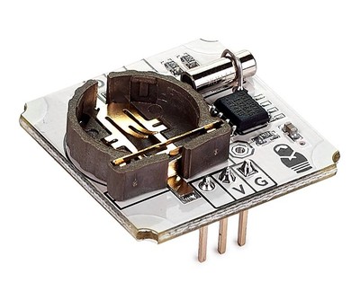 Let's try to write a more complex program in Tiny Basic - real time clock control of
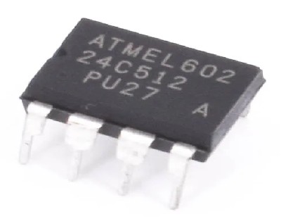 Another interesting chip with an I2C interface -